555 Timer Circuit Schematic - 555 Timer - Frequency and Duty Cycle Calculator - Online ... : The following schematic shows two additions to the basic 555 timer circuit.
byAdmin•
0
555 Timer Circuit Schematic - 555 Timer - Frequency and Duty Cycle Calculator - Online ... : The following schematic shows two additions to the basic 555 timer circuit.. Its name is derived from three 5k ohm resistors,connected in series used in it.the timer ic can produce required waveform accurately. 555 timer helpers schematic the addition of a capacitor to the trigger will not work for short output pulses as there Jun 11, 2017 · 555 timer circuits (133) browse through a total of 133 555 timer circuits and projects including the timer's datasheet. Jul 27, 2021 · over 100 of 555 timer circuits and projects including the ic datasheet. One reduces the trigger sensitivity and the other will double the output pulse duration without increasing the r1 and c1 values.
This pin connects to the negative side of the battery. With this information you will learn how how the 555 works and will have the experience to build some of the circuits below. 555 datasheet 555 duty cycle 555 metronome 555 reset function 555 time delay relay inverted 555 timer pulse generator. The 555 timer is a simple integrated circuit that can be used to make many different electronic circuits. These are easy to build 555 circuits for beginners and advanced engineers.
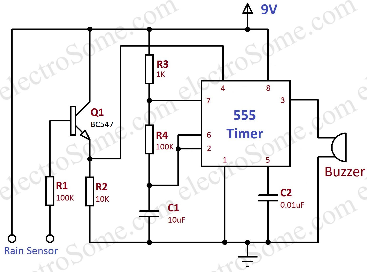
Rain Alarm using 555 Timer - Hobby Circuit from electrosome.com The output voltage from the chip is around 1.5 v lower than vcc when high and around 0 v when low. What is a 555 timer and how does it work? Feb 18, 2021 · 555 timer circuit in this time delay circuit, the threshold, pin 6 and the discharge, pin 7 are tied together at the junction of the rc timing components and the output remains low and stable until the 555 is triggered into action by the application of a negative pulse on pin 2. Its name is derived from three 5k ohm resistors,connected in series used in it.the timer ic can produce required waveform accurately. 555 timer helpers schematic the addition of a capacitor to the trigger will not work for short output pulses as there Over 100 of 555 timer circuits and projects including the ic datasheet. Jul 27, 2021 · over 100 of 555 timer circuits and projects including the ic datasheet. With this information you will learn how how the 555 works and will have the experience to build some of the circuits below.
This means that the output voltage is a periodic pulse that.
Jun 04, 2021 · 555 timer pinout. What are different modes of 555 timer? What are the applications of 555 timer? With this information you will learn how how the 555 works and will have the experience to build some of the circuits below. What is a 555 timer and how does it work? 555 datasheet 555 duty cycle 555 metronome 555 reset function 555 time delay relay inverted 555 timer pulse generator. This means that the output voltage is a periodic pulse that. 555 supply (pins 1 and 8). The following schematic shows two additions to the basic 555 timer circuit. There are simple circuits for beginners and advanced engineers. Its name is derived from three 5k ohm resistors,connected in series used in it.the timer ic can produce required waveform accurately. 555 timer tutorial bundle includes: Jul 27, 2021 · over 100 of 555 timer circuits and projects including the ic datasheet.
555 signals and pinout (8 pin dip) figure 1 shows the input and output signals of the 555 timer as they are arranged around a standard 8 pin dual inline package (dip). Jul 27, 2021 · over 100 of 555 timer circuits and projects including the ic datasheet. This pin connects to the negative side of the battery. The output voltage from the chip is around 1.5 v lower than vcc when high and around 0 v when low. There are simple circuits for beginners and advanced engineers.
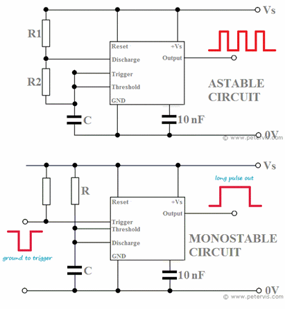
555 Timer Remembering Astable and Monostable Circuits from www.petervis.com What are the applications of 555 timer? The following schematic shows two additions to the basic 555 timer circuit. 555 timer helpers schematic the addition of a capacitor to the trigger will not work for short output pulses as there This pin connects to the negative side of the battery. 555 signals and pinout (8 pin dip) figure 1 shows the input and output signals of the 555 timer as they are arranged around a standard 8 pin dual inline package (dip). What are different modes of 555 timer? Jul 27, 2021 · over 100 of 555 timer circuits and projects including the ic datasheet. One reduces the trigger sensitivity and the other will double the output pulse duration without increasing the r1 and c1 values.
555 timer was first introduced by signetics corporation in 1971 as se555/ne555.
One reduces the trigger sensitivity and the other will double the output pulse duration without increasing the r1 and c1 values. 555 timer was first introduced by signetics corporation in 1971 as se555/ne555. The 555 timer is a simple integrated circuit that can be used to make many different electronic circuits. 555 signals and pinout (8 pin dip) figure 1 shows the input and output signals of the 555 timer as they are arranged around a standard 8 pin dual inline package (dip). The following schematic shows two additions to the basic 555 timer circuit. 555 supply (pins 1 and 8). What is a 555 timer and how does it work? 555 timer tutorial bundle includes: These are easy to build 555 circuits for beginners and advanced engineers. What are different modes of 555 timer? Over 100 of 555 timer circuits and projects including the ic datasheet. 555 timer helpers schematic the addition of a capacitor to the trigger will not work for short output pulses as there Feb 18, 2021 · 555 timer circuit in this time delay circuit, the threshold, pin 6 and the discharge, pin 7 are tied together at the junction of the rc timing components and the output remains low and stable until the 555 is triggered into action by the application of a negative pulse on pin 2.
Jun 11, 2017 · 555 timer circuits (133) browse through a total of 133 555 timer circuits and projects including the timer's datasheet. The output voltage from the chip is around 1.5 v lower than vcc when high and around 0 v when low. Mar 18, 2017 · 555 timer is an industrial standard ic existing from early days of ic. What are the applications of 555 timer? What is the maximum voltage that can be given to a 555 timer?
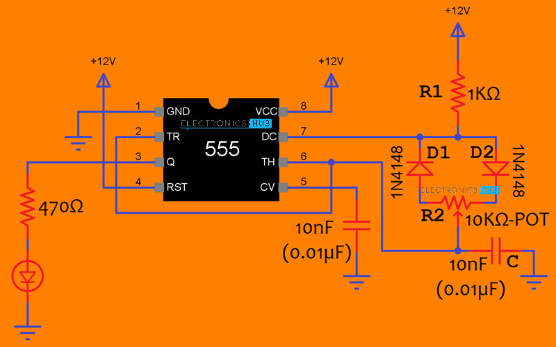
How to Generate PWM using 555 Timer IC? 555 Timer PWM Circuit from www.electronicshub.org There are simple circuits for beginners and advanced engineers. Mar 18, 2017 · 555 timer is an industrial standard ic existing from early days of ic. The 555 timer is a simple integrated circuit that can be used to make many different electronic circuits. This means that the output voltage is a periodic pulse that. The general 555 timer circuit schematic at the heart of the circuit is a lm555 ic, which includes 23 transistors, 2 diodes and 16 resistors on a silicon. What is the maximum voltage that can be given to a 555 timer? Jul 27, 2021 · over 100 of 555 timer circuits and projects including the ic datasheet. Jun 11, 2017 · 555 timer circuits (133) browse through a total of 133 555 timer circuits and projects including the timer's datasheet.
What is the maximum voltage that can be given to a 555 timer?
What are different modes of 555 timer? The output voltage from the chip is around 1.5 v lower than vcc when high and around 0 v when low. 555 signals and pinout (8 pin dip) figure 1 shows the input and output signals of the 555 timer as they are arranged around a standard 8 pin dual inline package (dip). What is a 555 timer and how does it work? Over 100 of 555 timer circuits and projects including the ic datasheet. With this information you will learn how how the 555 works and will have the experience to build some of the circuits below. These are easy to build 555 circuits for beginners and advanced engineers. The 555 timer is a simple integrated circuit that can be used to make many different electronic circuits. Jun 04, 2021 · 555 timer pinout. 555 datasheet 555 duty cycle 555 metronome 555 reset function 555 time delay relay inverted 555 timer pulse generator. What are the applications of 555 timer? 555 timer was first introduced by signetics corporation in 1971 as se555/ne555. Its name is derived from three 5k ohm resistors,connected in series used in it.the timer ic can produce required waveform accurately.
Jun 11, 2017 · 555 timer circuits (133) browse through a total of 133 555 timer circuits and projects including the timer's datasheet 555 timer schematic. With this information you will learn how how the 555 works and will have the experience to build some of the circuits below.